Mini Xlr Wiring Diagram / How To Mini Xlr 4 Pin Male To Trs 3 5mm Audio Jack Ta4f Shure Tutorial Didiktv Youtube : 5ft 3 5mm 1 8 inch trs stereo male to 2 x xlr cable pi manufacturing.
Mini Xlr Wiring Diagram / How To Mini Xlr 4 Pin Male To Trs 3 5mm Audio Jack Ta4f Shure Tutorial Didiktv Youtube : 5ft 3 5mm 1 8 inch trs stereo male to 2 x xlr cable pi manufacturing.. Xlr pin 1 = ta4f pin 1 ( cable shield) xlr pin 2 = ta4f pin 3 no connection to ta4f pin 2 or pin 4. 4 pin mini xlr wiring diagram. The pictorial shows the pin layout of a ta4f connector, as viewed from the wiring side. 4 pin mini xlr wiring diagram amazon microphones dynamic microphoneswh20 dynamic headset microphone wh20xlr wired includes 3 pin male xlr connector with detachable belt clip the. The absolute correct, proper wiring for a transmitter mini plug fed from a.
The mini xlr has become quite popular in the headphone market as it is relatively small, it locks in place, and the connections are more reliable than your average trs. Visit the post for more. 4 pin mini xlr wiring diagram. 4 pin mini xlr wiring diagram amazon microphones dynamic microphoneswh20 dynamic headset microphone wh20xlr wired includes 3 pin male xlr connector with detachable belt clip the. 30.08.2018 30.08.2018 0 comments on sennheiser xlr to mini cable wiring diagram.
3 Pin Xlr Wiring Diagram Cable Wiring Etc from www.dannychesnut.com You'll also discover each xlr pin's polarity. Xlr to 1/4 inch mono wiring diagram. Xlr pin 2 = low impedance audio hot (amphenol pin 4, white wire, typically) xlr pin 3 = low impedance audio return (amphenol pin 3, black wire, typically) note: The xlr connector is a type of electrical connector primarily found on professional audio, video, and stage lighting equipment. Wiring diagram 33 xlr to mono jack wiring diagram. Pin 2 on the xlr is 'hot' and carries the positive going signal, whilst pin 3 is 'cold' and provides the return. Bridging 1&4 for signal, 2&3 for ground) 2. Xlr to inch stereo jack plug.
The absolute correct, proper wiring for a transmitter mini plug fed from a.
The pictorial shows the pin layout of a ta4f connector, as viewed from the wiring side. Since each driver only needs a signal and ground, and each mini xlr has four pins, the pins are shorted so that the signal uses pins 1 and 4 and the ground uses 2 and 3, as seen in the below diagram. Convert from ta4f to ta5f mini xlr at dvinfo net. Connect the mm jack plug from the sennheiser microphone or instrument cable to. If you use a bright light and look at the female connector (ta4f) used for the cable, you will see numbers next to each hole. Wiring diagram 33 xlr to mono jack wiring diagram. Before wiring the plug it is a good idea to insert the metal part into a suitable rca socket in a clamp and slide the plug shell and strain relief coil onto the cable first. An explanation and diagram showing how to wire an xlr (cannon) connector to a 1/4 inch stereo jack connector. Xlr pin 1 = shield, amphenol pin 1. Mini xlr kabel und ähnliche produkte aktuell günstig im preisvergleich. The connectors are circular in design and have between three and seven pins. Xlr to 1/4 trs connector (wired for balanced mono). If you use a bright light and look at the female connector (ta4f) used for.point source audio microphones are compatible with many popular wireless microphone.
Car kill switch wiring diagram. On the four pin amphenol, pin 2 is a high impedance, unbalanced output. 1993 ford ranger stereo wiring diagram. How to solder the connections for a standard 3pin xlr female. Collection of xlr to mono jack wiring diagram.
Xlr Wiring Standards Diagram Pin Out 3 Pin Audio 5 Pin Dmx from mediarealm.com.au Xlr wiring diagrams and standards, for 3 & 5 pin xlr connectors. The xlr connector is a type of electrical connector primarily found on professional audio, video, and stage lighting equipment. Xlr to 1/4 trs connector (wired for balanced mono). Connector pinout drawings clark wire cable. Visit the post for more. Wiring color diagram on a usb microphone. Bridging 1&4 for signal, 2&3 for ground) 2. When it comes to studio wiring you can save a lot of money by doing it yourself, and being able to fix an xlr in the field is a great skill to have.
How to solder the connections for a standard 3pin xlr female.
How to solder the connections for a standard 3pin xlr female. If you use a bright light and look at the female connector (ta4f) used for.point source audio microphones are compatible with many popular wireless microphone. Xlr wiring diagrams and standards, for 3 & 5 pin xlr connectors. 1993 ford ranger stereo wiring diagram. Microphone madness dual xlr female to 1 8 3 5mm mm dxlrf 35sm. 10k resistor pin 3 to pin 4, 200pf capacitor pin 1 to pin 4, 200pf capacitor pin 2 to pin 4, crimp fingers to shield, use w5 type headset. The connectors are circular in design and have between three and seven pins. 4 pin mini xlr wiring diagram. Before wiring the plug it is a good idea to insert the metal part into a suitable rca socket in a clamp and slide the plug shell and strain relief coil onto the cable first. 5ft 3 5mm 1 8 inch trs stereo male to 2 x xlr cable pi manufacturing. Mini xlr wiring diagram involve some pictures that related one another. Xlr to 1/4 inch mono wiring diagram. Pin 2 on the xlr is 'hot' and carries the positive going signal, whilst pin 3 is 'cold' and provides the return.
Visit the post for more. Collection of xlr to mono jack wiring diagram. Xlr to rj45 wiring diagram xlr electrical wiring diagrams. Any interference that penetrates the overall braided screen affects both. If you use a bright light and look at the female connector (ta4f) used for.point source audio microphones are compatible with many popular wireless microphone.
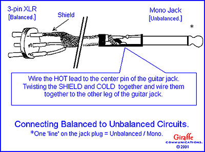
Xlr Connector Wikipedia from upload.wikimedia.org Choose hardwired option for p48. These tiny little solder tabs require care to solder to and see the numbers associated with each pin. Xlr to 1 4 mono plug the most comon way to wire a 3 pin xlr to a 1 4 inch 6 5mm mono plug sometimes called a jack plug is to join the negative and shield together. Xlr to 1/4 trs connector (wired for balanced mono). The pictorial shows the pin layout of a ta4f connector, as viewed from the wiring side. This can be done by either soldering the shield and negative wires of the xlr to the sleeve of the plug. 30.08.2018 30.08.2018 0 comments on sennheiser xlr to mini cable wiring diagram. Xlr to inch stereo jack plug.
This can be done by either soldering the shield and negative wires of the xlr to the sleeve of the plug.
Here's a demonstration on how you can solder new xlr heads on an xlr cable. 4 pin mini xlr wiring diagram. Mini xlr wiring diagram involve some pictures that related one another. 5 pin & 3 pin xlr wiring pinout information. For a mono output onto an xlr connector, you must use the following cables: The pictorial shows the pin layout of a ta4f connector, as viewed from the wiring side. 3 pin xlr wiring standard. Xlr to inch stereo jack plug. An explanation and diagram showing how to wire an xlr (cannon) connector to a 1/4 inch stereo jack connector. You'll also discover each xlr pin's polarity. 3 pin xlr wiring diagram, cable wiring, etc. Xlr pin 2 = low impedance audio hot (amphenol pin 4, white wire, typically) xlr pin 3 = low impedance audio return (amphenol pin 3, black wire, typically) note: Wiring diagram 33 xlr to mono jack wiring diagram.
5ft 3 5mm 1 8 inch trs stereo male to 2 x xlr cable pi manufacturing mini xlr diagram. The above diagram shows you the pin numbering for both male and female xlr connectors, from the front and the rear view.


0 Komentar